Minimum distances based on hole diameter
End and edge distance e1 , 2.0∙do where do is = hole diameter
Minimum end distance e1 , (with reduced bearing capacity) 1.2∙do where do is = hole diameter
Minimum edge distance – right angles to load (e2) 1.5∙do
-------------------------------------------------------------
Maximum end and edge distances
In any environment > 12∙t or 150mm
When exposed to weather or corrosion 40mm + 4∙t
-------------------------------------------------------------
Spacings between Bolts
In direction of load (p1) (Recommended) 3.5∙do
In direction of load (p1) (Minimum spacing) 2.2∙do
rows of fasteners (p2) (Recommended) 3.0∙do
-------------------------------------------------------------
Maximum spacing
In compression elements and outer row tension elements 14∙t or 200mm
Inner row tension elements 28∙t or 400mm
Note: t is the minimum thickness of the connected parts.
-------------------------------------------------------------
IStructE EC3 (Steel) Design Manual
Design resistance for bolts
-------------------------------------------------------------
fub is the strength of the bolt
fu is the strength of the element
Fv,Sd is the actual shear force on the bolt
Ft,Sd is the actual tensile force on the bolt
As is the tensile stress area of the bolt
d is the diameter of the bolt
γMb is the partial factor = 1.35
-------------------------------------------------------------
Reduction factor βp when using bolts through packings , βp = 9∙d / ( 8∙d + 3∙tp ) , but βp ≤ 1.0
whose thickness is greater than d/3
Table 14.3 Nominal yield strength and ultimate strengths for bolts
(used as characteristic values in calculations)
-------------------------------------------------------------
Bolt grade , 4.6 8.8 10.9
Yield fy, N/mm2 240 640 900
Ultimate fy N/mm2 400 800 1000
-------------------------------------------------------------
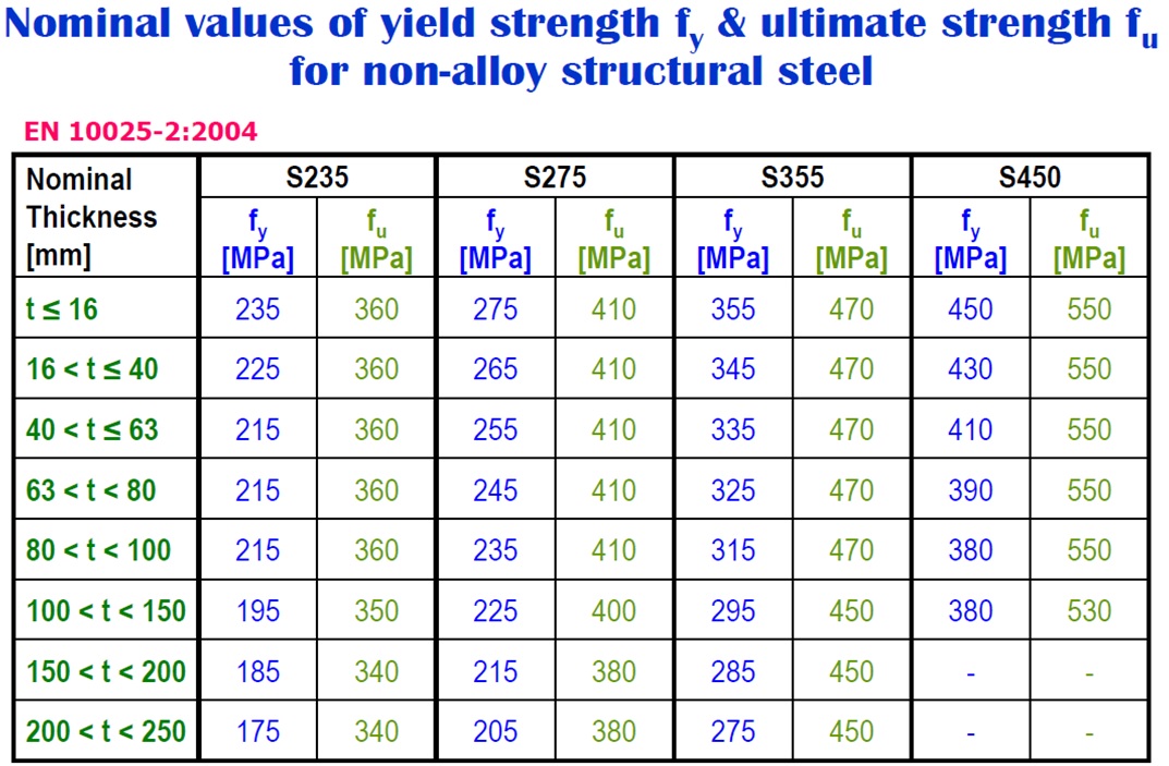
------------------------------------------------------------- Table 14.4 Nominal yield strength and ultimate strengths for steel
Steel grade t ≤ 40mm , 40mm < t ≤ 100mm
yield fy ultimate fu yield fy ultimate fu
N/mm2 N/mm2 N/mm2 N/mm2
S 275 275 430 255 410
S 355 355 510 335 490
------------------------------------------------------------- Note: t is the nominal thickness of the element
-------------------------------------------------------------